-
-
Lift the vehicle using a jack or stand so that the wheels are off the ground. Refer to your vehicle's owner manual for specific instructions on how to remove the stock shocks. Keep your original bolts to re-use when installing your new Elka shocks.
-
-
-
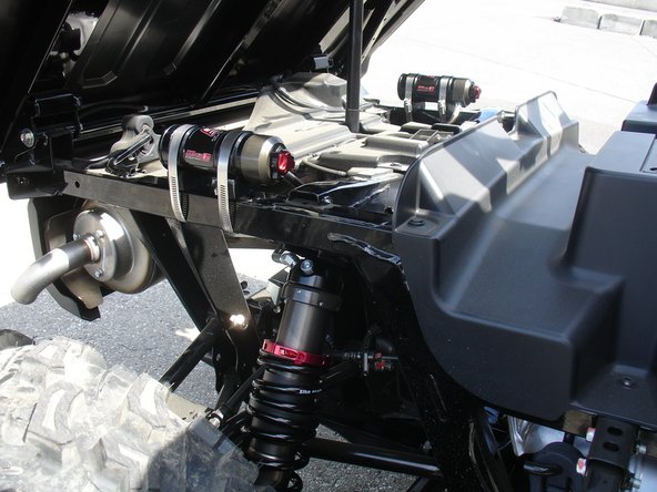
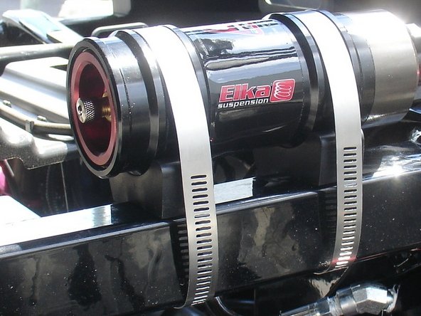
Install the front new Elka shocks with the reservoir ( on Stage 3-4-5 ) or Schraeder nitrogen valve ( on Stage 1-2 ) at the top of vehicle. ( left side shown ).
-
-
-
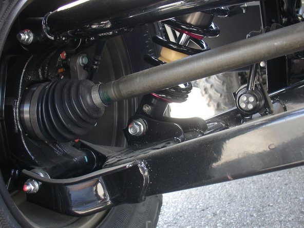
On Stage 2, Stage 4 and Stage 5 models, the lower shock eyelets should be installed with the rebound adjuster oriented towards the rear of the vehicle as shown by the blue Arrow on the photo ( Right side shown ). If needed, you can turn the lower eyelet to orient properly.
-
-
-
On Stage 1 and Stage 2, the left and the right shock are the same. Just install them with the shraeder nitrogen valve at the top of vehicle.
-
For the Stage 3-4-5, the remote reservoir shocks must be carefully installed without "over bending" the hoses during installation.'''
-
Note: The hose configurations are different on the left and right side, pay attention to pictures to make sure you are installing the proper shocks on each side.
-
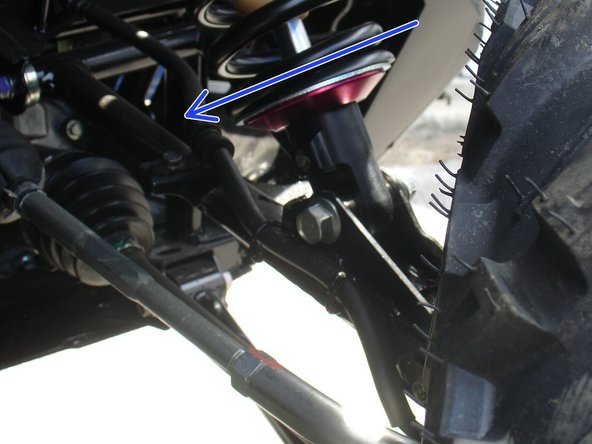
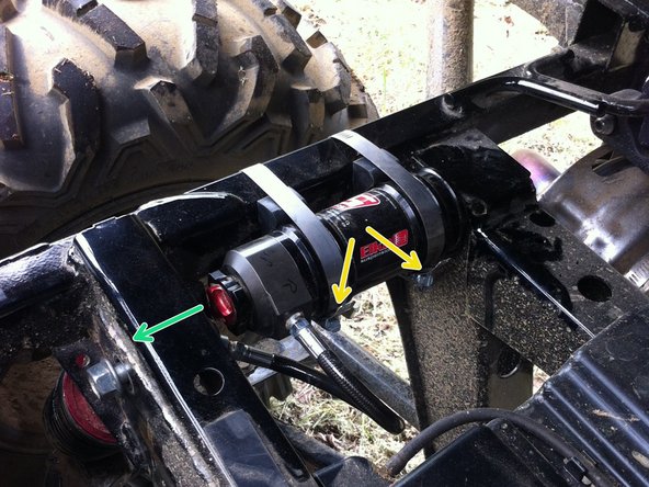
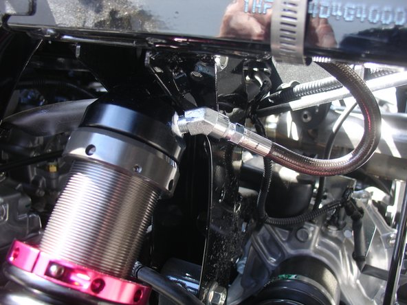
ON THE LEFT SIDE: When installed on vehicle with the shock head up: the left side shock hose is facing the rear of vehicle as indicated by the blue arrow, and go inward the frame.
-
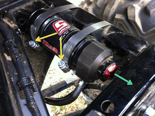
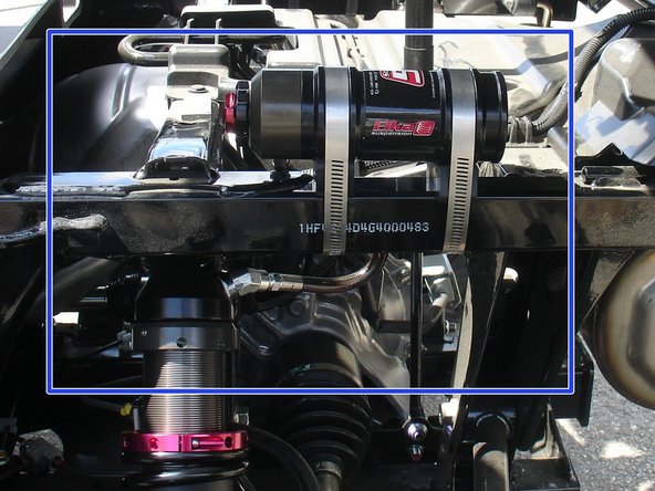
Route the hose properly and install the shock reservoir beside the frame as shown. Be sure the metal hose clamps screw are installed inward the vehicle as shown by the yellow arrows.
-
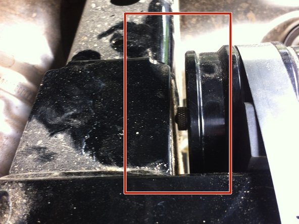
Note the reservoir knobs are facing the front of vehicle as shown by the green Arrow. The opposite side of reservoir can be installed very close of the frame to ensure enough space to turn the knobs. (See red rectangle)
-
IMPORTANT NOTE: Be sure the reservoir is not above the frame to be sure you can close the bed.
-
-
-
Note: The hose configurations are different on the left and right side, pay attention to pictures to be sure installing the shocks on the appropriate side.
-
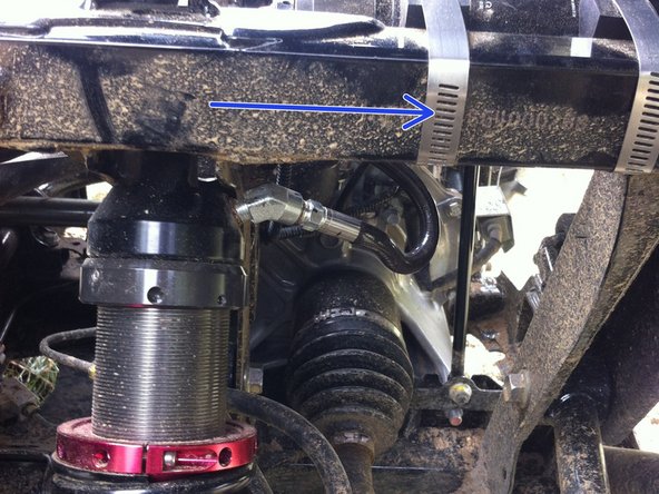
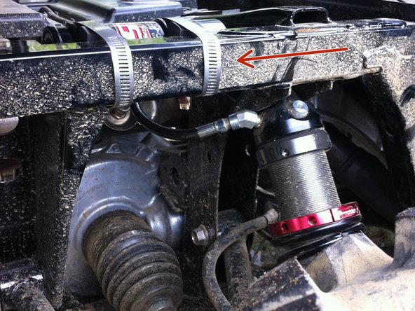
ON THE RIGHT SIDE: When installed on vehicle with the shock head up: the right shock hose is facing the rear of vehicle as indicated by the red Arrow, and go inward the frame.
-
Route the hose properly and install the shock reservoir beside the frame as shown. Be sure the metal hose clamps screw are installed inward the vehicle as shown by the yellow arrows.
-
Note the reservoir knobs are facing the front of vehicle as shown by the green Arrow. The opposite side of reservoir can be installed very close of the frame to ensure enough space to turn the knobs. (See red rectangle)
-
IMPORTANT NOTE: Be sure the reservoir is not above the frame to ensure you can close the bed.
-
-
-
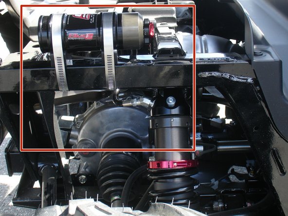
For Pioneer and Pioneer EPS without the seats in the bed, The reservoirs can by mounted over the frame as shown to allow a better access to compression knobs.
-
Picture with blue rectangle showing left side, and picture with red rectangle showing right side.
-
-
-
Install rubber mount between the frame and the reservoir, and slightly thight the metallic colars as shown.
-
Do not over bend hoses, avoid any kinks in the hose before thightening reservoirs in place
-
-
-
On Stage 2, Stage 4, and Stage 5 models the rebound adjuster located on lower eyelet of the shocks should be oriented towards the rear of the vehicle, as shown. (Left side shown ). If needed, you can turn the lower eyelet to orient properly.
-
Note: We highly recommend a tire pressure of ± 14 psi.
-