-
-
Lift the vehicle off the ground, then remove the front wheels.
-
Remove the bolt that holds the brake line on each side to ensure that it will not be damaged and stretched during installation.
-
Remove the sway-bar link on both sides to allow the lower arms to temporarily move separately.
-
-
-
Separate the upper control arms from the steering knuckle.
-
Separate the tie rod end from the steering knuckle.
-
Remove the lower shock nuts.
-
-
-
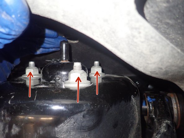
Remove the 3 upper shock nuts, except for the central nut.
-
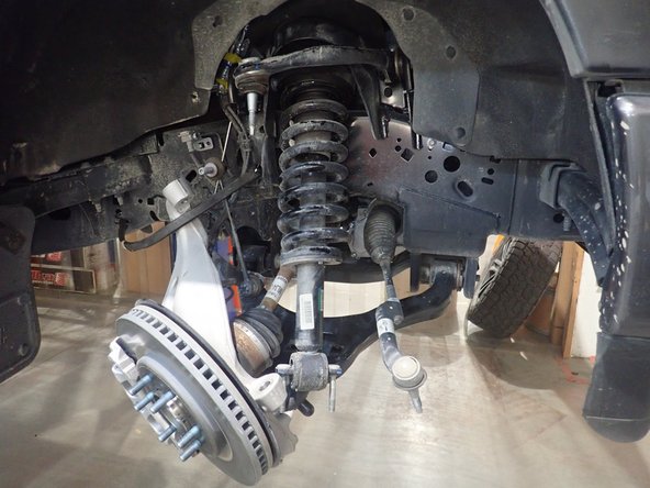
Remove the stock shocks.
-
-
-
ELKA SHOCKS WITH RESERVOIR:
-
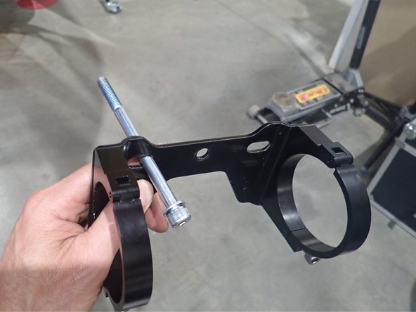
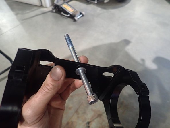
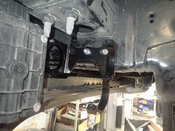
PASSENGER SIDE: Slide the small washer on the long 8mm bolt. Insert the bolt in the LEFT HOLE of the bracket assembly.
-
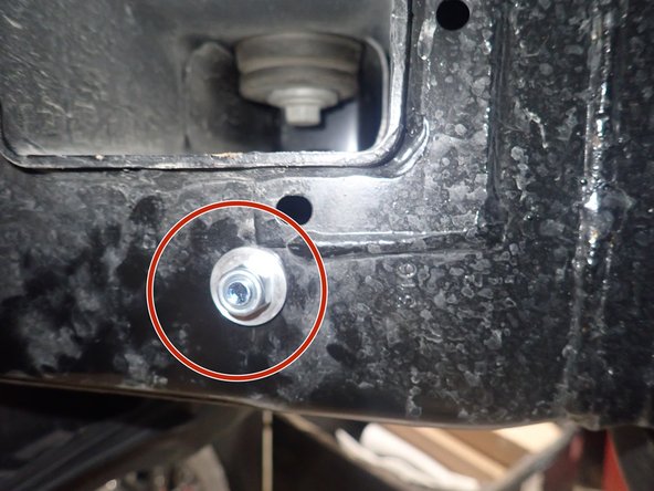
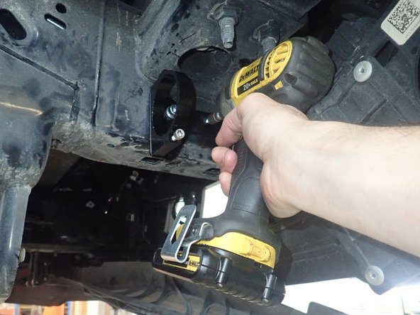
Slide bolt into frame hole as shown and fix the bracket with the larger washer and supplied nut. Torque nut to 20 Ft-Lb.
-
-
-
Orienting the bracket assembly as horizontally as possible, use the supplied self-taping screw to secure the bracket in the center bracket hole.
-
-
-
DRIVER SIDE: Slide the small washer on the long 8mm bolt. Insert bolt in the CENTER HOLE of the bracket assembly.
-
Slide bolt into the frame hole as in the previous step and fix the bracket with the larger washer and supplied nut. Torque nut to 20 Ft-Lb.
-
Orienting the bracket assembly as horizontally as possible, use the supplied self-taping screw to secure the bracket in the right bracket hole.
-
-
-
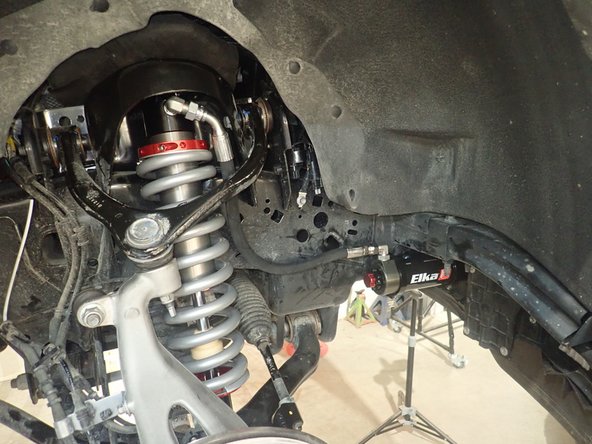
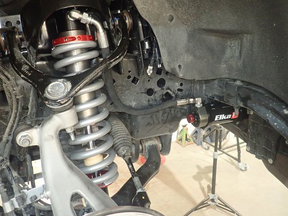
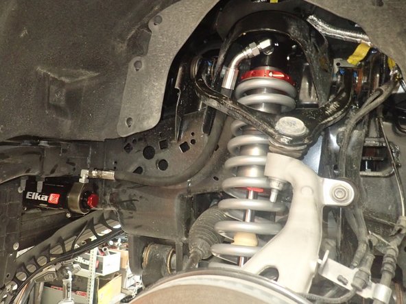
Install the Elka shocks using provided lower bolts and the provided upper bolts. Hoses must face the front of vehicle as shown (right side shown).
-
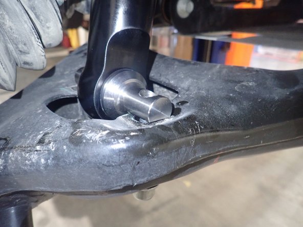
Make sure that the flat of the lower pin is against lower arm, as shown.
-
Apply thread locker, then torque the 3 upper bolts to 35 Ft-Lb, and the lower bolts to 60 Ft-Lb.
-
-
-
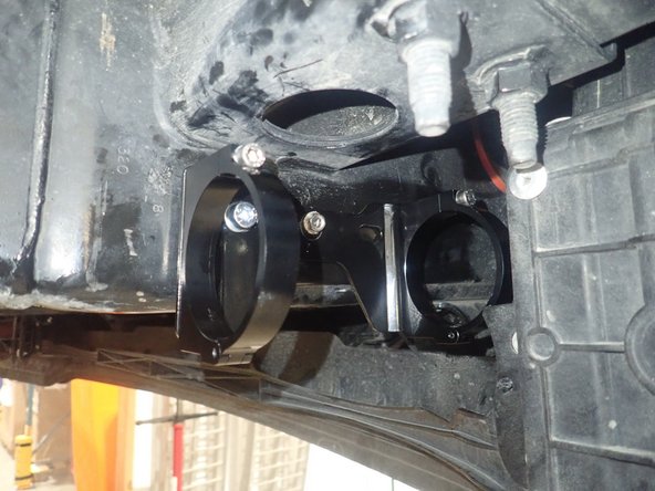
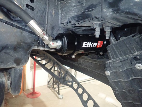
Sit the reservoir into the bracket clamps, then place the reservoir in such a way as to place the hose properly. BE CAREFUL TO NOT OVERBEND THE HOSE OR CREATE RUBBING ON FRAME.
-
When the reservoir is placed properly, apply thread locker on the clamp bolts and torque them at 10 Ft-Lb.
-
-
-
Reassemble the knuckle with the upper control arm. Torque the upper control arm nut to 70 Ft-Lb.
-
Reassemble the tie rod end, then torque the nut to 70 Ft-Lb.
-
Reassemble the sway bar link, then torque the nut to 70 Ft-Lb.
-
Reinstall the brake line bolts.
-
ALIGNMENT IS CRITICAL: A professional alignment must be performed before driving this vehicle at highway speeds. Do not attempt to drive your vehicle after this install without having the alignment readjusted to factory specs.
-
-
-
Lift the vehicle off the ground, then remove the oem shocks.
-
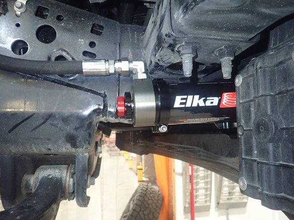
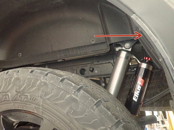
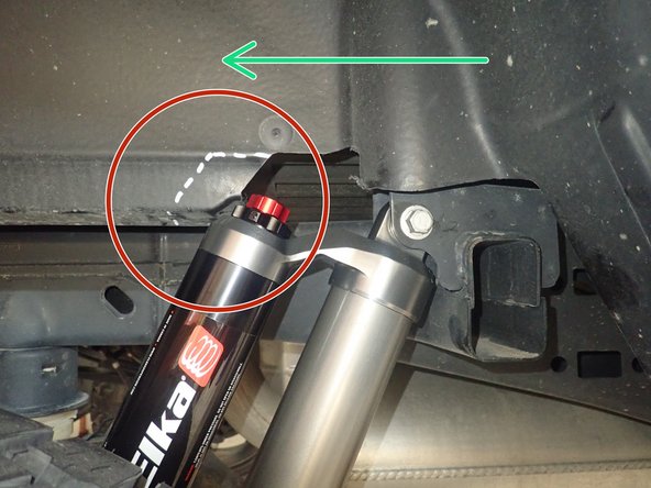
Both rear Elka shocks are the same, they must be installed with the piggyback reservoir facing up. The DRIVER'S SIDE reservoir must facing the REAR of vehicle as shown by red arrow, and the PASSENGER'S SIDE reservoir must facing REAR of vehicle as shown by green arrow.
-
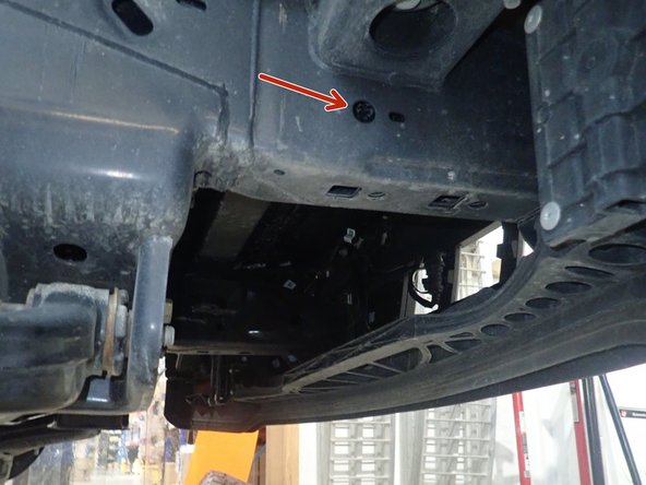
On the passenger's side, we reccomend to cut a small part of the plastic fender shown by the red circle to avoid damage to the shock's knobs in full compression.
-
Sit the vehicle on the ground, then torque all shock bolts at 80 Ft-Lb.
-
Installation complete.
-